Die4Drive –
A constant current laser diode driver with up to 2A output current.
Update
4/June/07
Moved to
Rev 1.2
This adds a
second POT to allow setting of threshold current.
This allows
setup to give output laser power proportional to input voltage.
Also added
a soft start feature.
These
modifications also make the drive slightly kinder to the laser diode.
Schematic for Rev
1.2 in PDF format.
Drive
current calculator in Excell Format for Rev 1.2
Picture of Rev1.1 and Rev1.2 side by side.
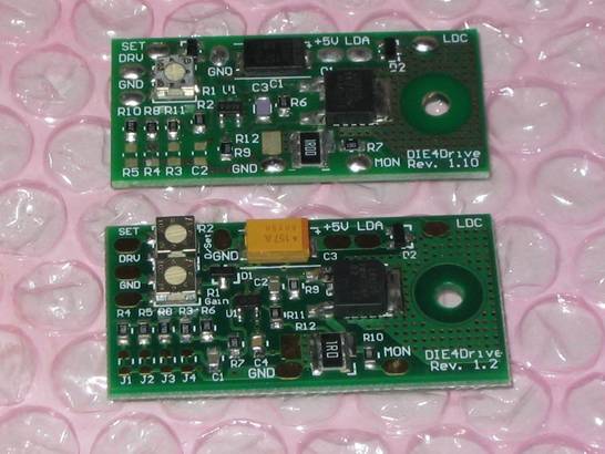
Rev
1.1 was 44mm x 20mm
Rev
1.2 is 44.5mm x 22.5mm
Rev 1.2 can
still have the sense resistor fitted as 0.1 Ohm for 10x current range (up to
2A)
Driver
supports CW, analogue or TTL modulation up to 200kHz.
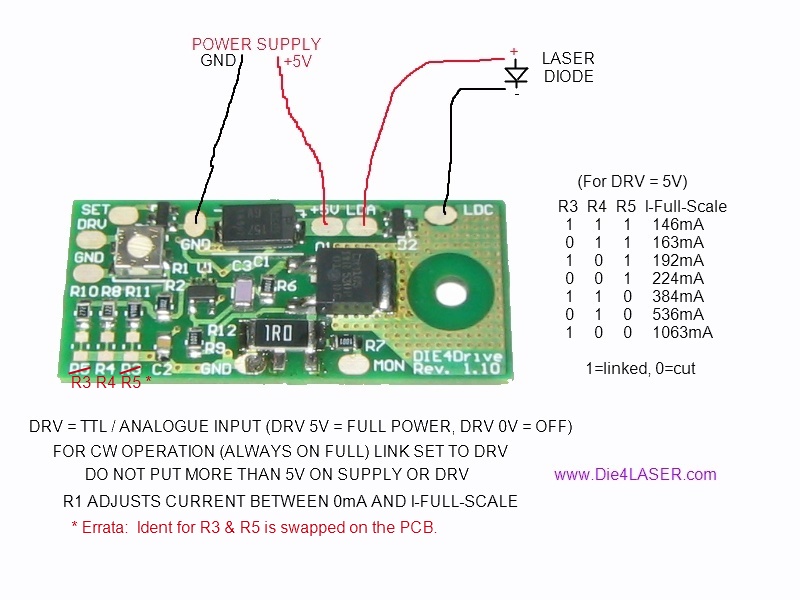
Connection
info for the driver board. Note the errata for V1.1 link resistor positions.
Up
to 300mA no cooling is required. Above
300mA the PCB may be bolted to a heatsink.
To
start with you will need a regulated 5V supply capable of the full diode
current.
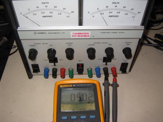
A
bench PSU will do – but a fixed 5V would be a lot cheaper.
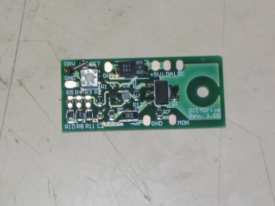
The
link resistors R5, R4 & R3 set the full scale current.
By
default all are shorted. This gives a
full scale current of 146mA.
The
Pot R1 sets the output from 0mA to full scale output.
The
full scale currents are as follows:
|
R3 |
R4 |
R5 |
I
Full-Scale (mA) |
|
|
|
|
|
|
1 |
1 |
1 |
146 |
|
0 |
1 |
1 |
163 |
|
1 |
0 |
1 |
192 |
|
0 |
0 |
1 |
224 |
|
1 |
1 |
0 |
384 |
|
0 |
1 |
0 |
536 |
|
1 |
0 |
0 |
1063 |
|
|
|
|
|
|
Above: 1 = linked
0 = cut |
|
|
|
The
drive current may be monitored by looking at the voltage on the MON pad.
MON
gives 1mV per mA, so for 100mA you would read 100mV from MON to GND.
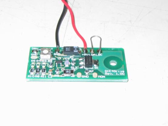
To
check the setup before connecting your diode you can short LDA to LDC.
The
driver will put the current through the short and you can monitor the MON pad.
For
CW operation DRV is linked to SET.
For
TTL / analogue drive DRV is the input from 0 to 5V.
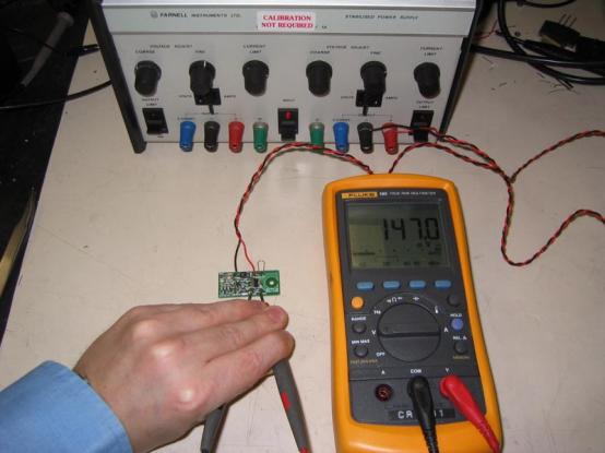
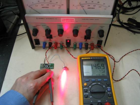
For
the DVD recorder laser diode the lowest range
is used. Here the pot is set at max.
The
current is 147mA into the shorting link.
Return
the pot to minimum, remove the shorting link LDA to LDC.
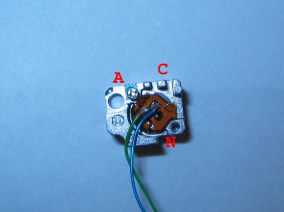
Connect
the laser diode. (Anode A to LDA, Cathode C to LDC, N is a no-connect)
**
Now is a good time to put on your laser safety goggles. **
Apply
power and slowly turn up the pot.
Still
reading 147mA with the pot at max.
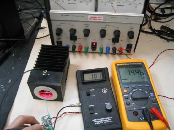
100mW
output at approx. 145mA drive.
Here
is a ‘scope capture of the output current with TTL modulation.
The
driver has R4 & R5 links cut to set a full scale of 1A.
(Do
Not put 1A through a DVD laser diode – it WILL kill it)
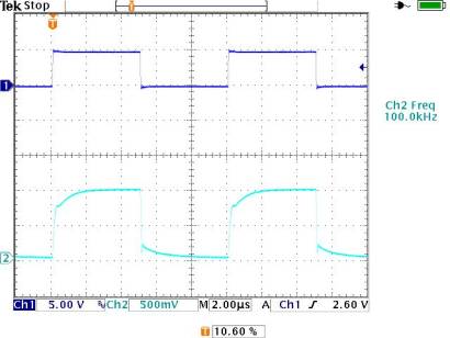
Ch.1
is 5V TTL I/P, Ch.2 is 500mA/div output current.
Nice and clean & no nasty spikes.