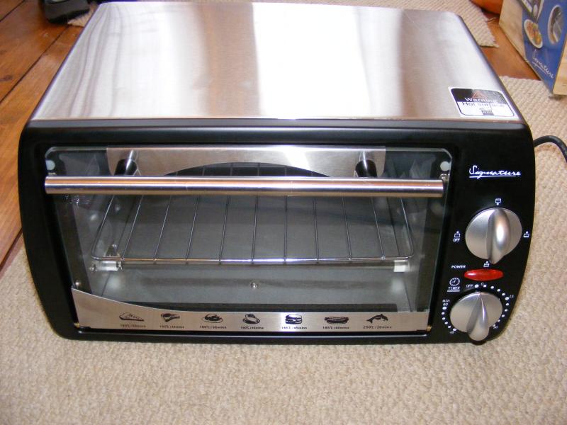
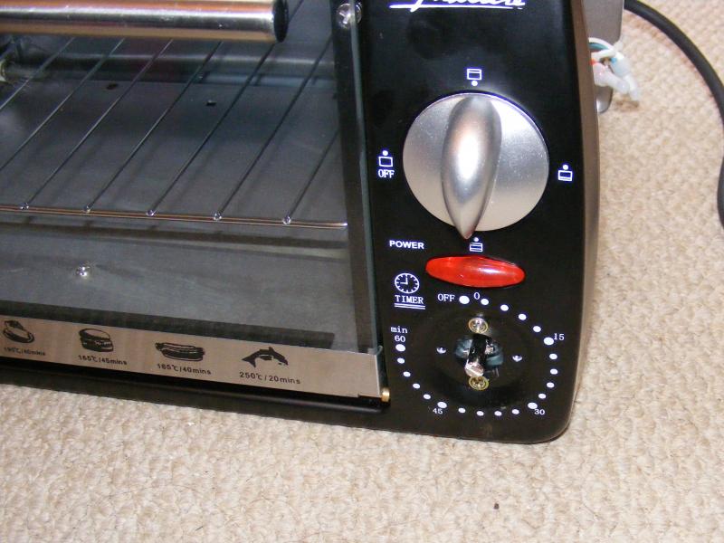
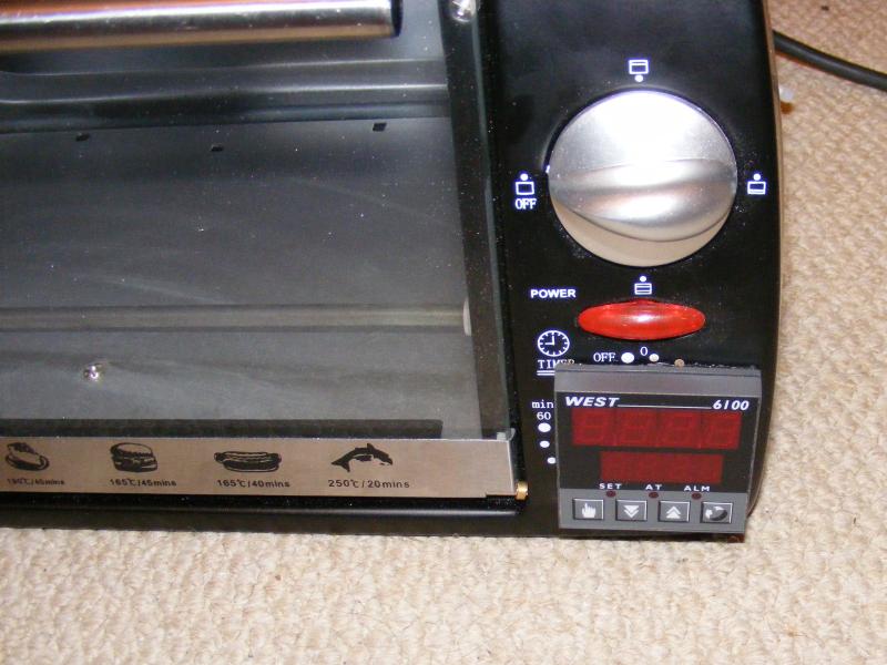
Pulling the lid revealed the clockwork timer with bell and above it the selector switch for top elements, bottom elements or both.
Probing this area with a thermocouple whilst the lid was still on revealed an air temp of over 100 degrees C. (not good for a PID controller)

The knob for the timer was forcibly removed revealing the screws for the time switch. This was taken out and a suitable hole cut for the PID controller.
A Dremel (or dremel clone) with a diamond slot cutting disk (£3 GBP for 3 on ebay) makes short work of the pressed steel front panel.
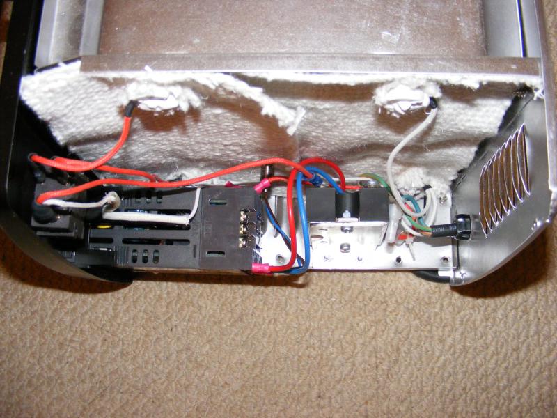
At this point before fitting the PID controller I decided to sort out that 100 deg C ambient temperature in this part of the oven.
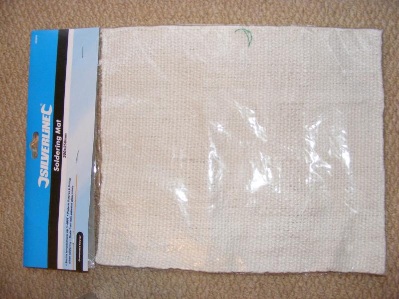
What you need is some high performance thermal insulation which is good for 300 deg C plus. I found something suitable in a local hardware store for under £4.
This mat is intended for plumbers to solder on and is good for 600 degrees C. One slight drawback is that the weave contains a small quantity of fine metal threads to help hold it together.
The mat should therefore be considered conductive and suitable clearance or insulation be applied between it and anything at mains potential.
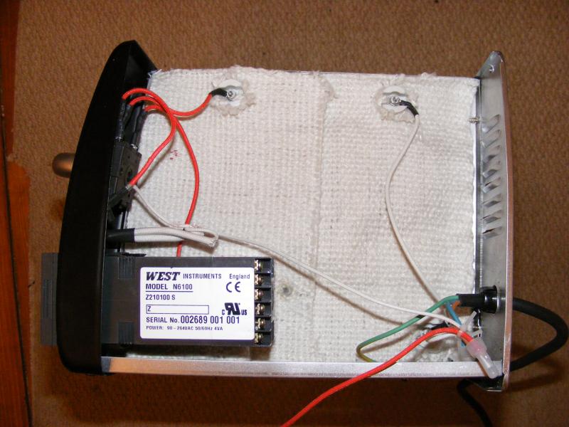
The wires to the heater elements were removed to allow fitting of the mat. Clearance holes were made in the mat by cutting a small cross aligned with the weave.
Ideally 2 layers of the thermal insulation should be used. The pack I bought gave 1 full layer and one partial layer on top.
As I mentioned earlier the mat should be considered electrically conductive so trim back the loose weave surrounding the ceramic element mounts.
The mat may be held in place by very small dabs of thermal RTV adhesive (make sure it is the 350 deg C type)
An additional 2.5mm hole was drilled to the right of the PID controller to pass the thermocouple wire through.
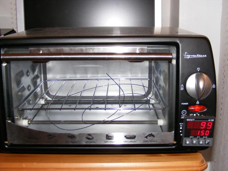
Viewed from the front now the PID controller is in place
Now the solid state relay was fitted on a piece of bent aluminium sheet. Also the vents in the case were bent further in to allow better airflow.
Lid back on and the conversion is complete. The element selector switch and Power ON neon have been retained.
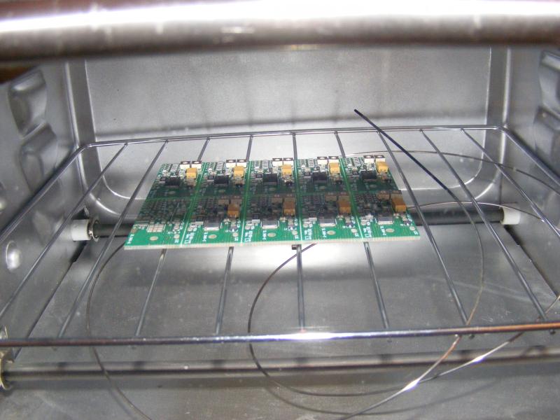
Note the excess thermocouple cable curled up under the wire rack. The thermocouple is a 1000 degrees C rated 1mm stainless steel K type.
This was another ebay special. You can buy them new on ebay with 100mm long probes ends rather than the 1m one I got. Price is approx $15.
I painted the end of the thermocouple probe with matt black Plasti-kote Hot Paint. See testing below.
Testing time....
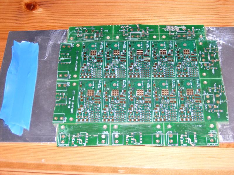
I screened a test board with solder paste and added a couple of representative components.
I put the PID controller in manual mode and slowly ramped up the temperature.
The lead free solder paste (Melting Point 217 Deg C) melted at an indicated 180 degrees C.
I put this down to the board temperature being higher than the air temperature measured by the thermocouple.
Ideally the thermocouple would be in contact with the PCB but this could be awkward to arrange and ensure consistency of contact from board to board.
The board is heated by infrared energy from the top and bottom elements. Spraying the thermocouple black makes it absorb some of the IR however it is still cooled by the ambient air.
With the black paint in place the indicated temperature at which the Lead Free solder melted was 190 C.
I think the easiest way to compensate for this is to set a fixed offset of approx. 30C on the reflow profile.
So an initial ramp to preheat at an indicated 150C then a heat to reflow with a maximum indicated peak of 220C.
I would suggest a calibration based indicated solder melt temperature on a representative test board whenever the PCB dimensions or layers / copper weight change significantly.
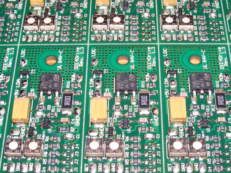
On my panel the temperature seemed fairly even across the board with the solder under all components reflowing within 5 seconds of each other..
Parts were from 0805 resistors to D-Pack MOSFETS.
I had to enter the temperatures manually with the PID controller up/down buttons. Some of the new PID controllers on ebay have 2 setpoints.
This would allow the dwell and reflow temperatures to be entered separately and swapped between using a switch or front panel control.
The measured temperature ramp rate was approx. 1 degree C per second. Whilst this is a little on the low side it can still achieve the desired result.
For most lead free processes you are allowed 60 to 150 seconds above the solder melt temperature. This would easily let you hit a peak of 245 C within 60 seconds.
*Remember to tune (or run auto-tune on) the PID controller else the ramp rate may be considerably lower.*
Ok - now on to putting down the solder paste.
The cheapest stencils are laser cut from polyester sheet. These are somewhat fragile so are not suitable for large production runs however their price makes them very attractive for prototype and small volume runs. At the time I bought mine a 21 x 22 cm piece of polyester (with 2 stencil designs laser cut on it) cost me £14 including shipping.
Quick plug here - only used the chap once but the price and service were great. http://www.smtstencil.co.uk/
To use the stencil you need some sort of jig to hold the stencil in place over the PCB. Avoid buying a jig of the shelf as most are intended for use with framed stencils.
A simple aluminium plate with scrap PCB glued around the outside can make a serviceable jig.
The purpose of the scrap PCB is to locate the PCB to be printed and to provide a level edge at the PCB height all the way around it.
This prevents the stencil from bending at the edges as you put the paste down.
Now you need a squeegee for applying the solder paste. Some of the manual pasting jigs come with a squeegee however the price for the cheapest on ebay is over $100 by the time you add shipping.
In the quest for a cheap solution I found that a £1 window paint scraper with retractable 90mm blade provided reasonable results.
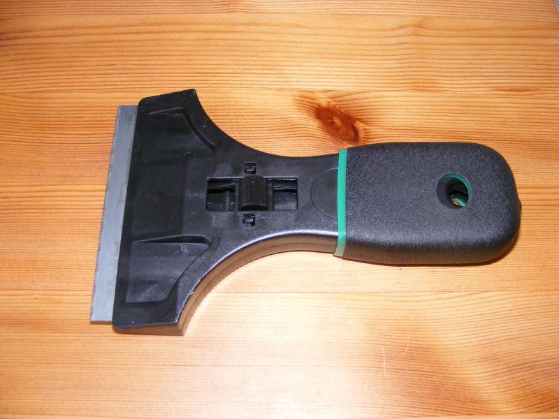
A little paste goes a long way. Using the scraper at a very shallow angle move it backwards to push the paste through the stencil.
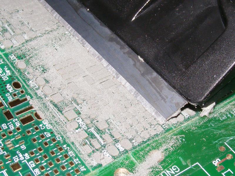
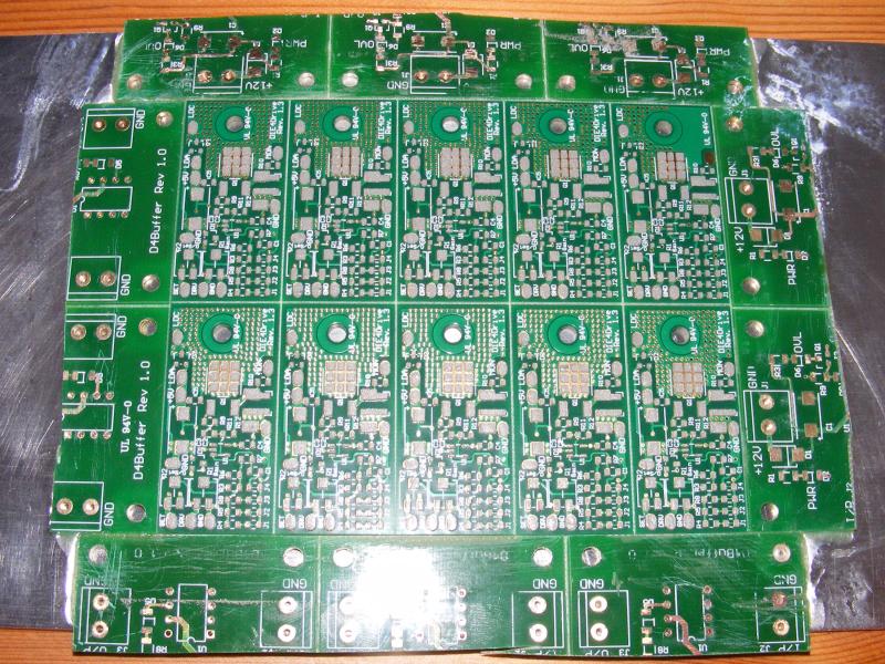
Once the panel is pasted you can carefully lift the stencil.
Now the components need to be put down. I find the best method is to drop the component lightly on to the paste then gently press down on it until it sinks a little.
Take care not to smudge the paste with your hands as you are placing components.
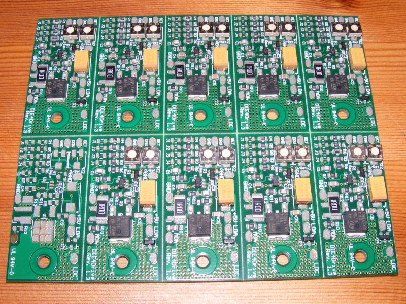
Now carefully transfer the board to the reflow oven. Knocking the board at this stage may dislodge several components.
Reflow the board and allow to cool. This particular oven has 3 latching positions for the glass door - open, closed and vented.
Once the oven hits peak reflow temperature I move the element selector switch to all elements off and also move the glass door to the vented position.
Once the temperature is below 140C I open the door fully. This method does not exceed the maximum recommended cool-down of 6 deg. C per second.
Once the oven is below 50C you can remove the board and admire your handiwork.
Usual disclaimers apply. The author of this page takes no responsibility for any damage to you or your property resulting from modifying a toaster oven.
Converting a toaster oven:
1) Voids the warranty.
2) Provides a possible electrocution hazard.
3) Provides a possible fire hazard.
Always check earth continuity to case after modification.
(Preferably PAT test the oven after modification.)
Never operate unattended
Back to the homepage